What is a gear?
A gear mechanism is a mechanism that transmits rotational motion by meshing teeth on two cylindrical surfaces.
Since this mechanism can reliably transmit a large amount of power, it is used to speed up or slow down rotation, increase torque, and change the direction of rotation. Here, the module that represents the type and tooth size of this gear. We will explain the characteristics of the tooth profile curve and the involute waveform that keep the angular velocity ratio of the gear constant.
Through this explanation, I hope that you can understand the analysis method of the angular velocity ratio of various gear trains and the mechanism of reduction gears and differential gear devices. In addition, knowledge of gear mechanisms is essential for understanding the mechanisms related to the structure of automobiles and industrial machinery, as well as basic knowledge for their development, application of functions, overhaul and repair, so I definitely recommend learning. .
table of contents
Gear configuration
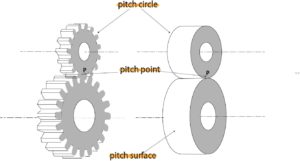
Figure 1: Gears and friction wheels
For example, friction wheels such as belt drives have advantages such as being quiet, smooth, simple in structure, and excellent in cost performance. The rotation speed ratio is inaccurate, and the friction surface is prone to wear and deterioration. If the contact force is increased to reduce the slippage, damage to the bearing and deformation of the friction surface will cause radius change. In order to solve these problems, gears are made by carving teeth on the friction surface of a friction wheel as shown in Fig. 1 so that rotation can be reliably transmitted by the meshing of the teeth.
The advantages and disadvantages of this gear are summarized below.
- Benefits of gears
- Can transmit large torque.
- The rotation ratio (gear ratio) can be kept constant and accurate.
- The load on the bearing is small.
- Disadvantages of gears
- Backlash occurs between teeth.
- Prone to noise.
- Since the shape is complicated and processing is difficult, the cost performance is poor.
Name of each part of the gear
Figure 1: Gears and friction wheels
- Names of gear parts from Fig. 1
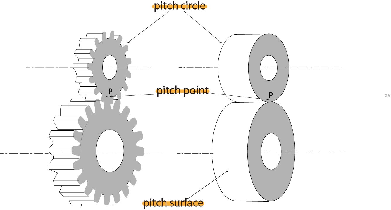
When a pair of gears are in mesh, the surface equivalent to the surface of a friction wheel that moves in the same way as the gears The surface seen from the front) is called the pitch surface.
When a pair of gears are in mesh, the gear circle corresponding to the outer circumference of the corresponding friction wheel is called the pitch circle.
When a pair of gears are in mesh, the point corresponding to the point of contact between the two friction wheels that move in the same way as the two gears (the gear teeth mesh point) is called a pitch point.
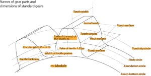
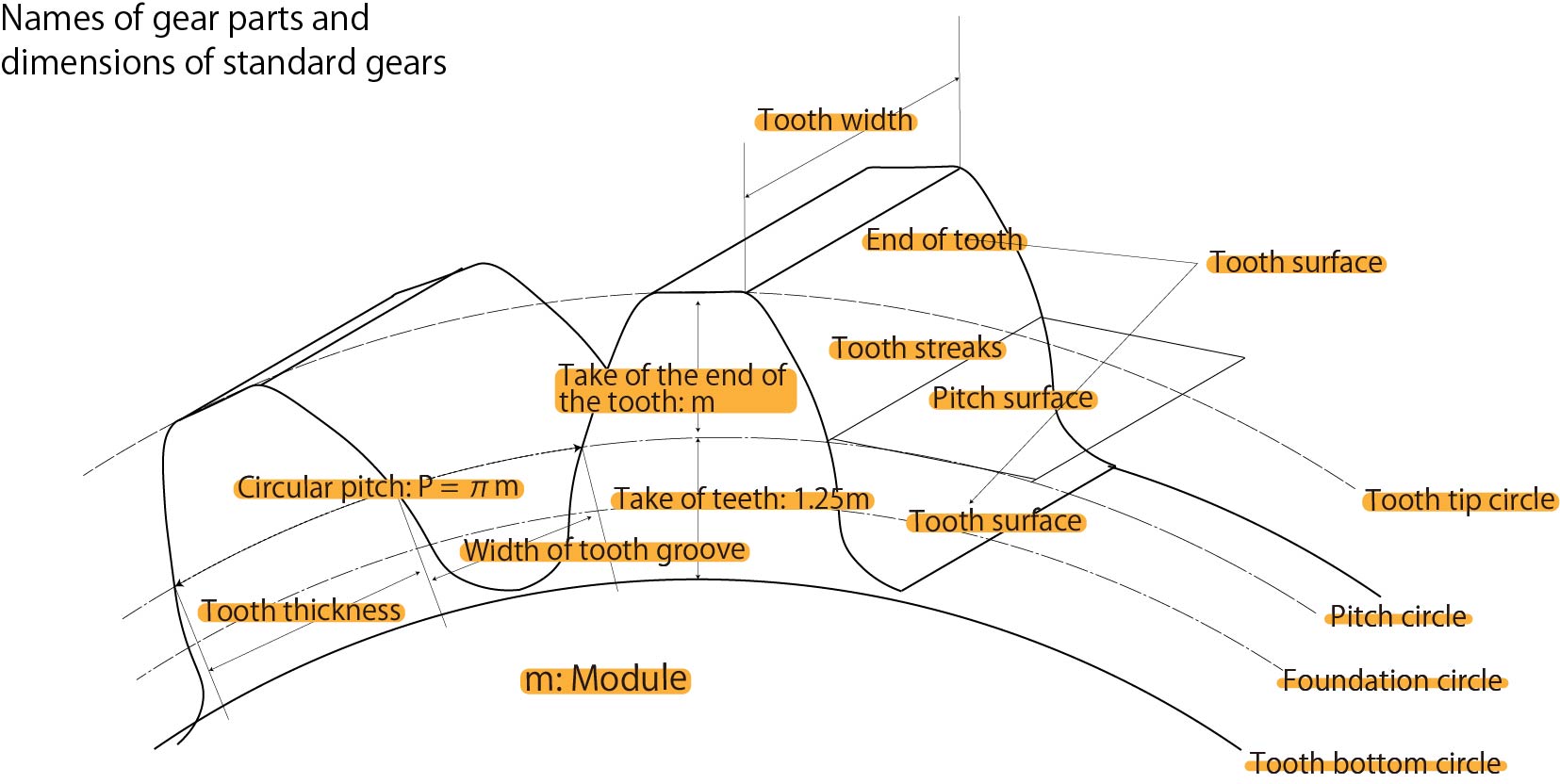
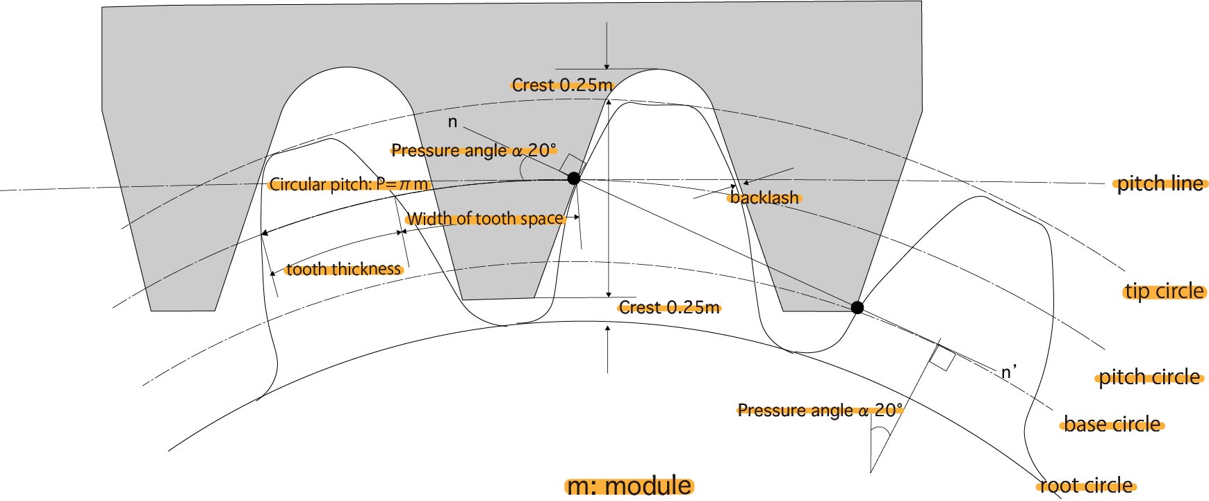
Figure 2-1: Names of gear parts and standard gear dimensions 1
- Names of gear parts from Fig. 2-1
- tip circle: circle passing through the tip
- root circle: circle through root
- Pitch circle: The circle corresponding to the friction wheel in Fig. 1 is the pitch circle, and the circle between the tip and root circles is Say.
- Tooth root height: Tooth height inside the pitch circle
- Addendum: Tooth height outside the pitch circle
- Total Tooth Height: Overall Tooth Height
- Tooth surface: Tooth meshing surface
- Tooth Width: Axial Tooth Length
Module and pressure angle
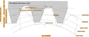
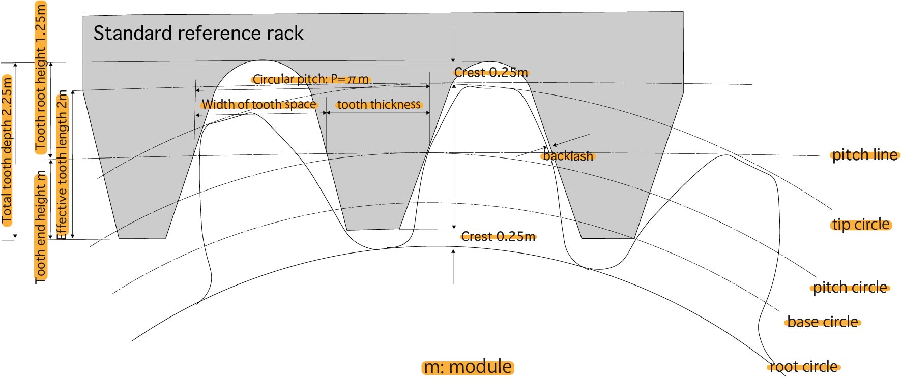
Figure 2-2: Names of parts of gears and dimensions of standard gears
Modules are used as references to represent tooth dimensions. If the pitch diameter is d (mm) and the number of teeth is z, the module m (mm) is defined as follows.
$$m=\frac{d}{z}$$
The value of the
module m is specified in the JIS standard. Generally used standard size teeth (full teeth) have the addendum height equal to the module, and the root height provides a gap (apex) between the tooth tip of the mating gear. It is stipulated that it should be 1.25m or more.
The effective tooth depth that contributes to tooth engagement is m on the addendum side and m on the root side, for a total of 2m.
In addition, the interval p between two adjacent teeth on the pitch circle is called the circular pitch, which is obtained by dividing the circumference of the pitch circle by the number of teeth.
$$p=\frac{πd}{z}=πm $$
In this way, the size and spacing of the teeth are all determined on the basis of the module.
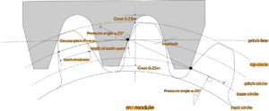
Figure 2-3: Names of parts of gears and dimensions of standard gears
The lengths of the teeth and grooves on the pitch circle are called the tooth thickness and the tooth groove width, respectively. In order for the gears to mesh without gaps, the tooth thickness and the width of the tooth groove must be half of the circular pitch p. Designed to fit. This is called backlash.
That is, the width of the tooth space is slightly larger than the tooth thickness.
Moreover, there is a pressure angle as a quantity representing the inclination of the tooth surface. The pressure angle α is defined as the angle formed by the common normal at the contact point of two gears and the direction of tooth movement (the direction of the common tangential line at the point of contact of two pitch circles). The pressure angle of is defined as 20°.
In this way, the size, interval and shape of the teeth of the gear are determined based on the module m and the pressure angle α, and the gears with the same module and pressure angle are meshed.
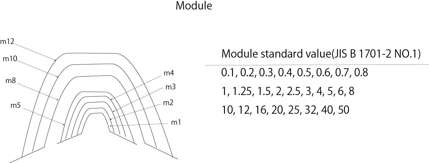
The standard values of modules and tooth sizes are shown below.

Figure 3: Module standard value and tooth size
Gear type
The many types of gears can be broadly classified into three types according to the relative positional relationship between the two gear shafts.
Parallel axis
Cylindrical gears with teeth on the cylindrical surface are used as the paired gears of the parallel shaft gears.
The most common of these is the spur gear, in which the tooth trace is parallel to the axis of rotation.

Fig.4-1: Spur gear
Spur gears are the most commonly used gears due to their easy policy.
In general, gears with teeth on the outside of the cylindrical surface are called external gears, and gears with teeth on the inside of the cylindrical surface are called internal gears.
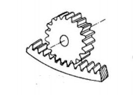
Fig.4-2: Internal gear
In addition, when two gears of different sizes mesh, the larger gear is called a gear (large gear) and the smaller gear is called a pinion (small gear).
Assuming that the diameter of a gear (large gear) is infinitely increased, it becomes a gear with straight teeth, which is called a rack.
The combination of racks and pinions can convert linear and rotary motions to each other.

Figure 4-3: Rack
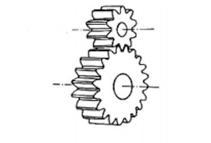
Gears that are machined so that the tooth trace is not parallel to the axis of rotation include helical gears and double helical gears.
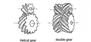
Figure 4-4: Helical gear and double helical gear
Because helical gears and helical gears are stronger than spur gears, the transition from one tooth to the next is smoother, and vibration and noise are reduced, they are used for applications such as high-speed rotation often
Crossing axis
When two axes intersect each other, there are straight bevel gears with curved tooth traces, and spiral bevel gears with curved tooth traces. .
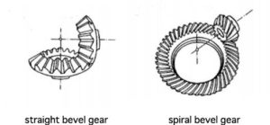
Fig. 4-11: Straight bevel gear and spiral bevel gear
A bevel gear with a cone angle of 90° is called a crown gear.
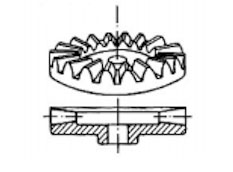
Fig.4-6: Crown gear
Discrepancy axis
If the two
axes are neither intersecting nor parallel, they are called staggered axes.
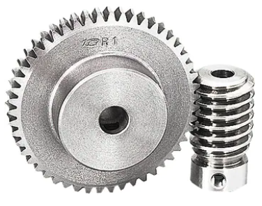
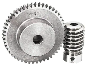
When the two axes are at right angles, rotation can be transmitted by a worm shaped like a screw and a worm wheel that meshes with it. This combination is called a worm gear.
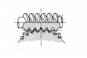
Fig.4-9: Worm gear
The worm gear can obtain a large angular velocity ratio, but cannot transmit rotation from the worm wheel to the worm.
also. Gears that transmit rotation when the two axes are not perpendicular include helical gears and hypoid gears that use helical gears and spiral bevel gears as their staggered axes.
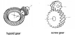
Fig.4-10: Screw gear and hypoid gear
Gear tooth curve
for gear tooth curve. There is a mechanism for smoothly transmitting rotation.
- The gear teeth. While the contact point slides, it transmits rotation at a constant angular velocity ratio.
- An involute gear has a constant angular speed ratio regardless of the number of teeth.
Gear engagement
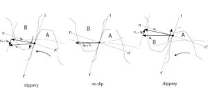
Figure 5: Gear contact
If you look at how one tooth of the gear meshes, you can understand that rotation is transmitted while sliding along the contact point tooth profile curve. Fig. 5 shows the velocity of gears A and B at the contact point
$$\upsilon{_A},\upsilon{_B}$$
and sliding velocity of B relative to A
$$\upsilon{_B}-\upsilon{_A}$$
It shows a
.
The sliding velocity is the common tangent at the contact point
$$t-t’$$
Parallel to
.
The locus of the contact point on the tooth profile curve (gray line in Fig. 5) is longer on the addendum side than on the dedendum side (with the pitch line as the boundary), and the contact point on the addendum side moves relatively fast.
When the contact point is on the pitch circle,
$$\upsilon{_A}-\upsilon{_B}$$
It becomes
, and it is in a state where there is no slippage.
The tooth profile curve is designed to satisfy the constant angular velocity ratio condition so that the angular velocity of the gear does not change during this sliding contact.
The curve most often used as a tooth profile curve is an involute curve.
Figure 5: Gear contact
Involute curve

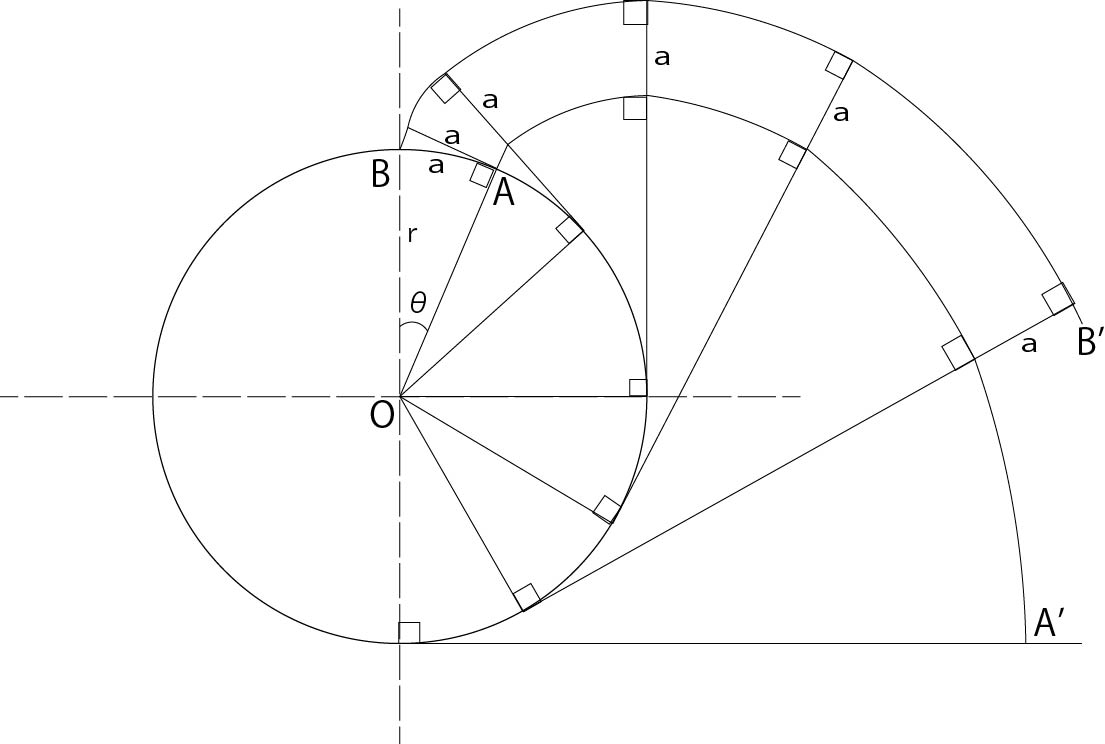
Figure 6: Involute curve and normal pitch
As shown in Figure 6, when a thread wound around a circle is unwound without slack, the trajectory drawn by the tip of the thread is called an involute curve, and the circle around which the thread is wound is called a base circle. .
Curves AA’ and BB’ in Fig. 6 are the trajectories of the tip points when the threads wound on the same base circle are unwound from A and B, respectively. The line of this locus is the involute curve.
$$\stackrel{\frown}{AB}=α=rθ$$
has the following properties
- Two involute curves and a thread intersect perpendicularly at any position, and the distance between the involute curves is equal to α at any position.This distance α is called the normal pitch.
- When the involute curve AA’ is rotated by θ around the center O of the base circle, it overlaps with BB’. That is, it can be said that the two involute curves are congruent.
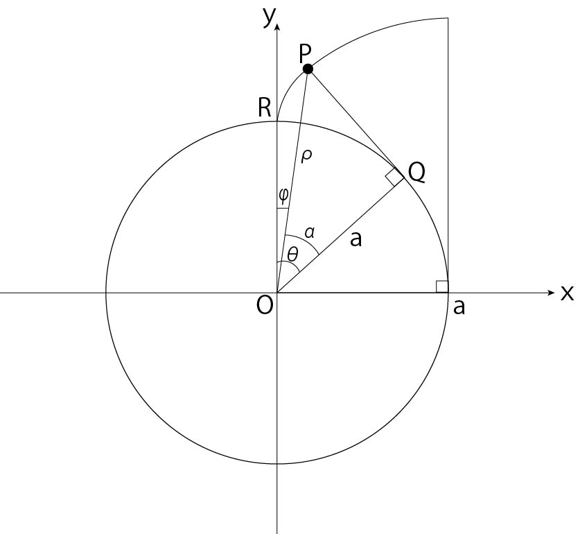
For example, suppose the equation of an involute curve with a base circle of radius α shown in FIG. 7 is expressed in the following two ways.

Figure 7: Involute curve
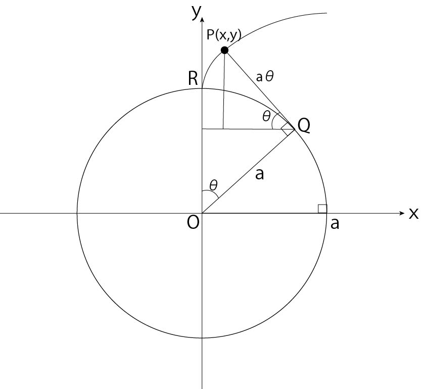
- Express the coordinates \((x, y)\) of point P using \((α, θ)\).
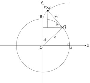
Figure 7-a: Coordinates (x, y) of point P are represented by a, θ
From Figure 7-a
$$\vec{OP}=\vec{OQ}+\vec{QP}…..①$$
Since the length of line segment AB in \(\triangle{OQS}\) is,
$$\vec{OQ}=\begin{pmatrix}a\sin\theta\\ a\cos\theta\end{pmatrix}$$
In addition, since \(\triangle{TQP}\) is regarded as a line segment \(QP=arc\stackrel{\frown}{QR}\) and its length is \(a\theta\)
$$QP=\stackrel{\frown}{QR}=a\theta$$
Therefore, line segment \(QP=a\theta\) at \(\triangle{TQP}\)
$$\vec{QP}=\begin{pmatrix}-a\theta\cos\theta \\a\theta\sin\theta \end{pmatrix}$$
can be expressed as
From ①
$$∴\begin{pmatrix}x\\y\end{pmatrix}=\begin{pmatrix}a\sin\theta-a\theta\cos\theta \\a\cos\theta+a\theta\sin\theta \end{pmatrix}$$
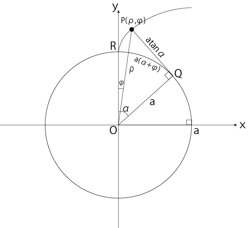
- The polar coordinates \((\rho, \phi)\) of point P are expressed using \(a, α\).

Figure 7-b: The polar coordinates (ρ, φ) of point P are represented by a, α
In \(\triangle{OQP}\) in Figure 7-b
$$\rho\cos\theta=\alpha$$
$$∴\rho=\frac{\alpha}{\cos\alpha}$$
Length of arc \(\stackrel{\frown}{QR}\) = line segment \(QP\), so
$$\stackrel{\frown}{QR}=QP$$
in short
$$a(\alpha+\phi)=a\tan\alpha$$
$$\phi=\tan\alpha-\alpha$$
Therefore
$$∴\begin{pmatrix}\rho\\\phi\end{pmatrix}=\begin{pmatrix}\frac{\alpha}{\cos\alpha}\\\tan\alpha-\alpha\end{pmatrix}$$
Also, \(inv(\alpha)=\tan\alpha-\alpha\) is called an involute function.
Note: In Fig. 7-a, the line segment \(QP=arc\stackrel{\frown}{QR}\) is possible because when point Q is fixed and point P is brought closer to point R, the line segment This is because the length of QP is infinitely close to the length of arc QR \((=\alpha\theta: radian method)\). It can be approximated by a line segment \(QP=arc \stackrel{\frown}{QR}\).
Involute gear
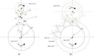
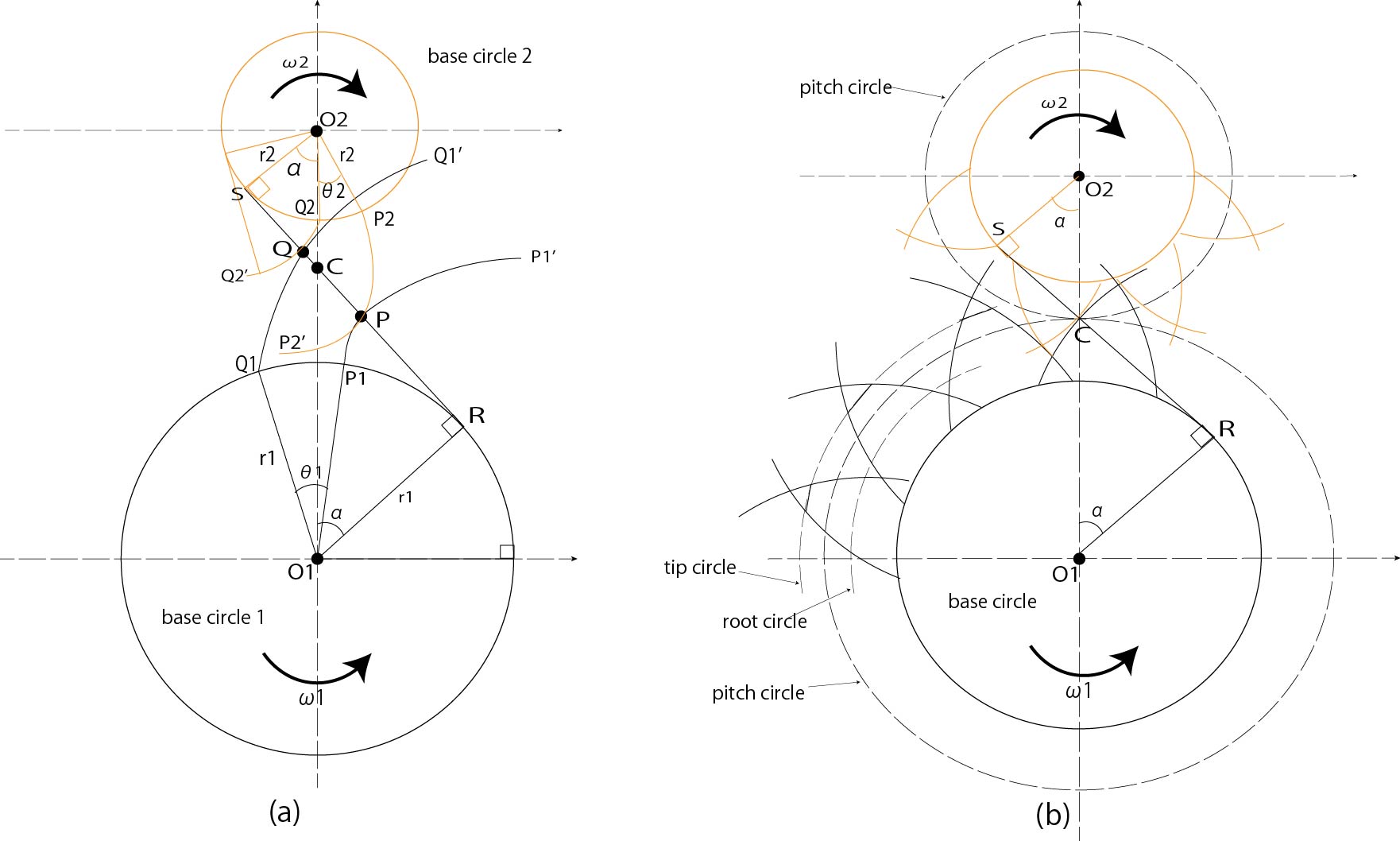
Figure 8: Transmission with involute tooth profile
If two gears with involute tooth profiles are rotated while they are in contact, the angular velocity ratio will be constant. This can be confirmed as follows with reference to FIG.
- As shown in Fig. 8-a, put the thread on the two circles \(O{_1},O{_2}\) in an S shape without bending.
- Cut the thread at point P, and involute curve \(P{_1}-P{_1′},Q{_1}\) with circle \(O{_1},O{_2}\) as the base circle Draw \(-Q{_1′}\).
- Splice the thread again and rotate the circle \(O{_1},O{_2}\) to send the thread from point P to point Q.
- Cut the thread at point Q, and create an involute curve \(Q{_1}-Q{_1′},Q{_2}\) with the circle \(O{_1},O{_2}\) as the base circle Draw \(-Q{_2′}\).
At this time, involute curves \(P{_1}-P{_1′}\) and \(P{_2}-P{_2′}\) are rotated together with each base circle while touching , the curves coincide with \(Q{_1}-Q{_1′}\) and \(Q{_2}-Q{_2′}\), and the contact point is on the straight line RS from P to Q move to
If the rotation angle of each base circle is \(\theta{_1},\theta{_2}\), the following relationship holds.
$$\stackrel{\frown}{P{_1}Q{_1}}=PQ=r{_1}\theta{_1}=r{_2}\theta{_2}$$
$$∴\frac{\theta{_2}}{\theta{_1}}=\frac{r{_1}}{r{_2}}$$
The common normal at the
contact point is always the straight line RS.
Therefore, the straight line \(O{_1}O{_2}\) connecting the common normal of the contact point and the center of the circle intersects at a fixed point C, satisfying the constant angular velocity ratio condition.
$$\frac{\omega{_2}}{\omega{_1}}=\frac{O{_1}C}{O{_2}C}=\frac{r{_1}}{r{_2}} (constant)$$
Therefore, if a gear is made with a tooth profile curve that is part of an involute curve as shown in Fig. 8-b, it will continue to rotate with a constant angular velocity ratio.
Such gears are called involute gears.
In addition, if a circle with a radius of \(O{_1}C,O{_2}C\) is taken as a pitch circle, it can be seen that the following three transmissions are all the same.
- Training transmission when the thread is wrapped around the base circle in an S shape
- Rolling transmission by pitch circle
- Contact transmission of gear with involute curve tooth profile
Figure 8: Transmission with involute tooth profile
Cycloid gear
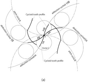
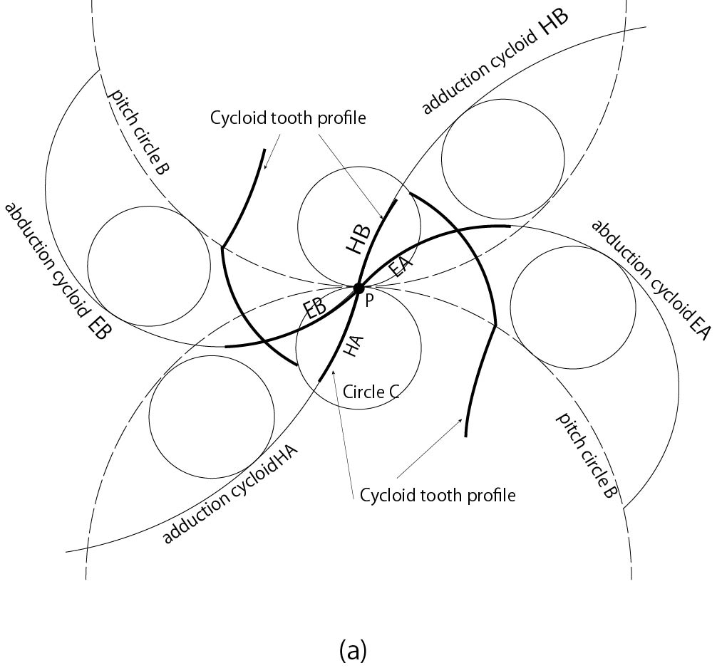
Fig.9-a: Transmission by cycloid tooth profile
When another circle rolls on a circle or a straight line, the trajectory drawn by a point on the rolling circle is called a cycloid curve.
A cycloid is called an abductor cycloid when it rolls outside the circle, and an adductor cycloid when it rolls inside a circle.
As shown in Fig. 9-a, circles A and B are the pitch circles of gears A and B, respectively, and P is the contact point.
When a small circle C rolls from a point P along the pitch circles A and B, the abductor cycloids are EA and EB, and the adduction cycloids are HA and HB.
A gear with tip EA and root HA and a gear with tip EB and root HB are called cycloid gears.
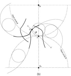
Fig.9-b: Transmission by cycloid tooth profile
As shown in Fig. 9-b, when the two tooth profile curves are brought into contact at point Q and a normal line \(n-n’\) is drawn, the pitch circle will always contact Since the point P intersects the curve connecting the center \(O{_A}O{_B}\) of the circle, the angular velocity ratio is constant. The trajectory of the contact point is an arc\(\stackrel{\frown}{PQ}\).