Stress and strain
table of contents
What is stress?
The stress is the force per unit area generated in the member. The force per unit area is the force applied per 1 mm (square millimeter) here.
For example, when a rod with a cross-sectional area of 10 mm is pulled with a force of 100 N, the force (stress) per unit area generated in the rod at that time is calculated as follows.
$$ Stress (sigma) σ=\frac{Pulling force P}{Bar cross-sectional area A}=\frac {100N}{10㎟} = 10N/㎟$$
Stress uses the symbol σ (sigma).
Load transfer
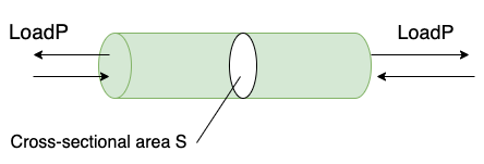
Figure 1: Load transfer
As shown in Fig. 1, a load of size P acts on both ends of the rod. At this time, the load acting on a certain surface outward in the direction of pulling the surface is called a tensile load, and the load acting in the direction of pressing the surface is called a compressive load.
The tensile load and compressive load acting on this rod are also called axial forces.
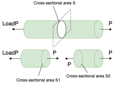
From Fig. 2, the loads P of the same size are acting on the rod in opposite directions in a staggered manner. Since the sum of the external forces on this rod is 0, the balance of forces on this rod is maintained. Consider a cross section S inside this bar that is perpendicular to the length of the bar. (Cross section S)
Assuming that the rod is cut at the portion of the cross section S, a load of the same magnitude P acts on the two cut surfaces S1 and S2, and the force balance is maintained even on the two left and right rods cut. Dripping. In other words, when considering the action of the internal force of the rod that receives the load in the opposite direction at both ends as shown in Fig. 2, the load P of the same magnitude is obtained no matter where the rod is cut so that the external force is transmitted. It can be seen that it acts as a force (internal force) acting inside the rod.
That is, the fact that the object is stationary without moving means that the resultant force of the forces applied to the object is balanced at 0. At first glance, it may seem that no force is applied to the object, but in reality, force is applied to the inside and outside of the object, and the resultant force is zero.
Normal stress and compressive stress

Figure 3: Tensile loads and stresses
From Fig. 3, consider the case where a tensile load is applied to both ends of the rod. Considering the force (stress) σ acting per unit area from the load P acting on both ends of the rod and the cross-sectional area A of the rod,
$$Stress: σ=\frac{load P}{cross section A}=\frac{P}{A}$$
Will be.
Here, since the unit of load is N (Newton) and the unit of cross-sectional area is ㎡, the unit of stress is N / ㎡, which is per unit area for any cross section on the surface of the object or inside the object. Can be defined as the force acting on. The stress acting in the direction perpendicular to the stress-acting surface is called normal stress.
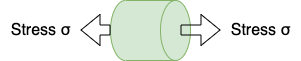
Figure 4: Normal stress
As shown in Fig. 4, the stress acting in the direction of pulling the stress acting surface vertically is called tensile stress, and the stress acting in the direction of pressing it perpendicularly to the surface is called compressive stress.
Shear stress
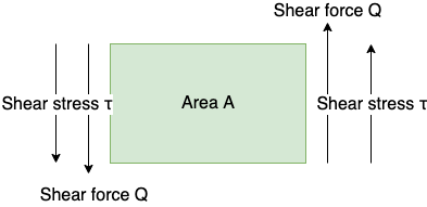
Figure 5: Shear force and shear stress
From FIG. 5, the force acting in parallel and at the same time in alternating directions with respect to a certain surface is called Q as a shearing force. This shear force Q expressed as a force per unit area is called shear stress. If the area of a certain surface is A, the shear stress τ can be defined by the following equation.
$$Shear stress:\tau=\frac{shear force Q}{area A}={Q}{A}$$
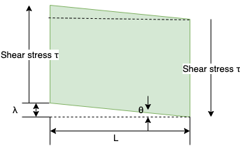
Figure 6: Shear stress and shear strain
Here, in FIG. 6, consider the ratio of the amount of shear deformation to the reference length. Here, the amount of shear deformation refers to the amount of strain on the surface caused by the action of shear stress. Deformation in the direction parallel to the square surface in Fig. 5 as shown in Fig. 6, where L is the length of one side of the surface (square) that is in a state where there is no change at the moment when the shear stress in Fig. 5 acts. Assuming that the amount is λ, the ratio of L to λ is the shear strain.
$$Shear strain:\gamma=\frac{\lambda}{L}$$
At this time, if the shear change amount λ is much smaller than L, the following relational expression holds between these lengths and angles θ.
$$\tan\theta\approx\theta=\frac{\lambda}{L} …… ① $$
From this equation, the shear strain can be regarded as the shear change amount λ expressed in an angle (rad = radian). This is because θ in Fig. 6 is the central angle, and L is regarded as the arc of the circle and the amount of λ changes.
$$tan\theta=\frac{\lambda}{L} …… ② $$
Here, if the amount of change in λ is very small, from ① and ② in the above equation.
$$tan\theta=\frac{\lambda}{L}\approx\theta$$
Because it can be considered.
Hooke’s law holds between the shear stress τ and the shear strain λ.
$$Hooke’s law for shear deformation:\tau=G\lambda(proportional constant G: shear modulus)$$
- Hooke’s law
The law that the elongation of an elastic object such as a spring and the load below the elastic limit are directly proportional (the law of elasticity).
The law is that force is proportional to elongation, load is directly proportional to elongation, and the following equation holds.
$$F = kx$$
Where x is an extension or contraction from the natural length. The natural length is the position where the unloaded spring stops naturally.
F is the force applied to the spring and is the reaction force due to the spring.
k is a constant called a spring constant, which has a value peculiar to the spring and indicates the strength of the spring itself.